

Combining the Israeli safety-factor requirement with European anchor design
12 בJuly 2026
What anchor is suitable for my stone cladding?
12 בJuly 2026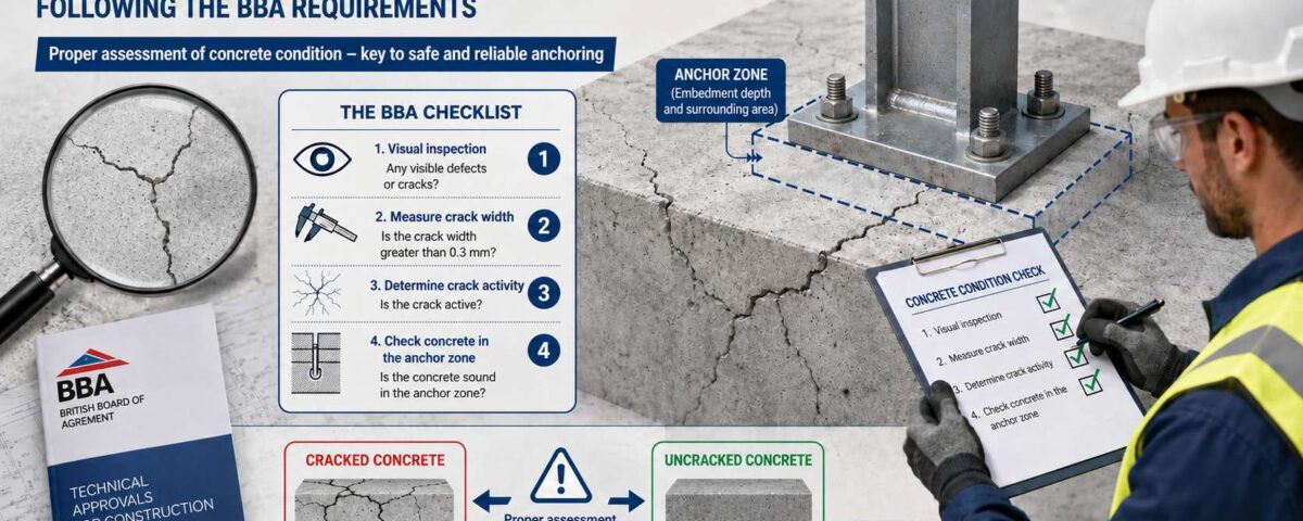
Deciding whether to treat the concrete as cracked or uncracked is one of the most consequential decisions in anchor design. It sets not only which anchor may be used, but how much load that anchor is allowed to carry. Guidance No. 39 of the British Board of Agrément (BBA) is the “Other Guidance” document required under the old European approval route ETAG 001 for mechanical anchors in concrete, and it gives practical rules for making that call. What follows is a full English treatment of the guidance, with the clarifications that were missing from earlier abbreviated versions.
Why this matters to the designer and to the installer
The guidance is not about whether cracks are visible to the eye. It is about the probability that a new crack will form in the anchor zone, or that an existing crack will widen, during the service life of the anchor. Where the zone can be classified as uncracked, a mechanical anchor approved for uncracked concrete only — a wedge anchor, typically — is normally acceptable. Where cracked concrete cannot be ruled out, the anchor must hold an ETA that covers cracked concrete, and in practice that usually means a chemical anchor.
Scope of the guidance, and “young” concrete
The guidance applies to anchors holding a European Technical Approval under ETAG 001, installed in new or existing structures, once thermal movement and drying shrinkage of the concrete have substantially ceased. These two movements do not stop over the same period, and earlier translations collapsed them into a single blanket figure, which is wrong:
- Thermal movement — the more significant of the two — may be assumed to have ceased 28 days after casting.
- Shrinkage depends on the aggregate. With low-shrinkage aggregates, significant shrinkage may be assumed to have ceased after 56 days; with other aggregates, 90 days is the more appropriate figure.
The guidance also assumes that the design, the detailing and the execution of the structure comply with the relevant regulations — in particular that movement joints have been provided where required, and that the reinforcement detailing follows accepted good practice.
The official definition of “uncracked concrete”
Four probabilistic principles sit underneath the definition:
- The resistance of the anchor is not governed by cracks present at the moment of installation, but by the future movement of those cracks. Only loads applied to the anchor after installation are relevant here.
- Loads on floors and soffits vary in time and in place, so any realistic statement about load has to be expressed as a probability.
- The load carried by the anchor is generally independent of the load on the structure as a whole — which makes this a joint probability of two separate events.
- Cracks in concrete appear at more or less regular spacings. Whether a particular anchor happens to land on one is, again, a matter of likelihood.
The full standard definition
Uncracked concrete is concrete in which there is a reasonably low probability that new cracks will form after the anchors are installed, or that the width of existing cracks will increase significantly during the service life of the anchors and at a depth that is significant relative to the embedment depth of the anchor.
That is a theoretical definition, written to compress all of the considerations above into one sentence. In practice, design on site relies on the simpler working rules set out below.
Deemed-to-satisfy provisions and the standard formula
According to the BBA, the requirement of the definition may be assumed to be met without any calculation at all, in certain structural elements and at defined locations within them — see Table 1 below. The fail-safe method of ETAG 001 states the following condition for assuming uncracked concrete:
σ1 + σχ ≤ 0
where:
- σ1 is the stress in the concrete produced by external loads, including the anchor loads themselves, with compression taken as negative.
- σχ is the stress in the concrete produced by restraint of internal and external imposed deformations, such as thermal movement and shrinkage.
In the Table 1 diagrams it is assumed that σχ is zero, so that only the zones that may be in compression are classified as uncracked. In pre-stressed elements, where the internal stresses are known far more precisely, a larger part of the element can be classified as uncracked. Likewise, in unrestrained elements such as cantilevers, the tensile capacity of the concrete itself may be used to extend the zones that count as uncracked.
Table 1 — partial list of uncracked concrete locations by structural element
The BBA presents nine common structural element types and, for each of them, the zones — along the element and through its cross-section — that may be assumed uncracked without calculation. The rule of thumb: hogging (negative moment) zones over supports, meaning the top of continuous slabs and beams, and the bottom face between supports, are generally in compression and therefore uncracked; sagging (positive moment) zones at mid-span, near the bottom face, are in tension and therefore counted as cracked.
| Structural element | Zone that may be assumed uncracked |
|---|---|
| Solid slabs — simply supported | A zone at each end of the span, 0.15L in from each support. |
| Beams — simply supported | A narrow band at the top of the section, 0.4h deep, within the 0.15L zones at the supports. |
| Continuous slabs and beams | 0.15L at the outer ends, plus 0.25L on each side of every internal support. |
| Ribbed floors | As for a solid slab, with the T-section of the ribs taken into account. |
| Cantilevers — slab or beam | A top band across the full width, from the supporting wall out to 0.25L along the cantilever. |
| Columns and internal walls | The whole cross-section, except around the perimeter of the ground floor and of the top floor. |
| Portal frames | The corner (haunch) zone, 0.15L, and the apex zone, 0.25L, provided adjacent spans differ by no more than 15%. |
In the original diagrams, L, L1, L2 and L3 denote the relevant span lengths and h the depth of the section. For the exact dimensions, consult the source document linked at the foot of this page.
Application to existing and refurbished structures
The Table 1 diagrams are written primarily for new structures, but they may also be applied to existing, decanted and refurbished structures, subject to two cumulative conditions:
- A structural appraisal has been carried out by a qualified engineer, confirming that the structure is in reasonable and stable condition with no significant deterioration.
- There is no significant increase in the load on the structure after the anchors are installed.
An existing structure that stays in use
In an existing structure that remains in normal use — that is, without decanting the occupants — anchors may be installed at any location, including zones that Table 1 does not mark as uncracked, provided no significant increase in structural load is expected after installation. This is a relatively permissive clause, and it recognises that a structure in continuous, satisfactory service is normally in a stable state as far as loading is concerned.
Practical summary — how this affects anchor selection
| Condition of the concrete | What it means probabilistically | Suitable anchor type |
|---|---|---|
| Compression zone per Table 1 (deemed-to-satisfy) | Reasonably low probability that a crack forms or widens | Mechanical anchor for uncracked concrete (lower cost, fast installation) |
| Large tensile zone, high tension on the anchor, or sagging moment at mid-span | Raised probability of a crack forming or widening significantly, in width and in depth, relative to the anchor | Anchor holding an ETA for cracked concrete |
| Existing structure in normal use, no load increase | Structure stable in loading terms — exempt from the defined locations | Uncracked-concrete anchor, at any location, subject to engineer’s appraisal |
| Uncertainty, or exact calculation required | No deemed-to-satisfy assumption available | Cracked concrete as the safe default |
Frequently asked questions about Guidance No. 39
Is concrete with visible cracks automatically “cracked concrete” under the definition?
Not necessarily. The standard definition addresses the likelihood that a new crack appears in the anchor zone, or that an existing one widens, after installation — not the mere presence of cracks visible at the time of installation. Where there is doubt, ask an engineer about the specific zone.
What is the difference between σ1 and σχ in the formula?
σ1 is the stress from external loads, including the anchor loads themselves. σχ is the stress produced by restraint of internal and external movements, thermal and shrinkage among them. The Table 1 diagrams take the conservative assumption that σχ is zero, so only clear compression zones are classified as uncracked.
Can an uncracked-concrete anchor be used in any existing structure?
If the structure remains in normal use rather than being decanted, no load increase is expected, and a qualified engineer has confirmed that the structure is stable and that a crack significant in width and depth relative to the chosen anchor is unlikely — then yes. If the structure has been decanted for refurbishment, you must also keep to the locations defined in Table 1, in addition to those two conditions.
What if the zone cannot confidently be established as uncracked?
In the absence of an exact calculation or an engineer’s advice, the safe default is to treat the concrete as cracked and select an anchor with an ETA for cracked concrete — usually a chemical anchor. The reasoning behind that default, and where we think it is applied too broadly, is set out in the second half of this page.
This article is a translation and adaptation of BBA Guidance No. 39, Anchor Bolts for use in concrete — UK Guidance: Distinction between cracked and non-cracked concrete, Issue 4, April 2015, British Board of Agrément. The English source document is the binding text; where the two differ, the source prevails.
Download BBA Guidance No. 39 (PDF, English)
What the standards actually say
Almost every anchor calculation opens with the same question: is the concrete cracked or not. The answer moves the calculated resistance by tens of percent, and often decides whether the connection is feasible at all in the diameter and embedment you had planned. In practice most designers tick “cracked” by default — not because they checked, but because the standard puts the burden of proof on them, and the information needed for that proof is almost never in their hands.
Two standards define the term here, and they are consistent with one another. EN 1992-1-1 sets the permissible crack width in service; for most reinforced concrete in ordinary exposure conditions that is 0.3 mm. EN 1992-4, clause 4.7, states that concrete shall be taken as cracked unless proven otherwise, and its reference crack is that same 0.3 mm.
What neither standard says matters just as much: neither of them defines a depth for the crack. A surface crack a few millimetres deep is enough to trigger the classification, while the qualification test the anchor has to pass creates a crack that runs through the full thickness of the element. The standard triggers the classification on one geometry and measures the resistance under an entirely different one.
How much load does it take to open a 0.3 mm crack
This question is asked far too rarely. Crack width is governed by the steel stress in the tension reinforcement and by the reinforcement detailing — bar diameter, spacing and cover. Put the numbers in, and a 0.3 mm crack at the face of the element corresponds to a steel stress at the top of the range permitted in service, not to the everyday load the element actually sees.
Put differently: the reference condition around which the whole classification system is built is not the normal state of a structure in service, but a relatively extreme one. It is nevertheless applied to every anchor, in every element classified as cracked.
The crack is a wedge, not a slot
A flexural crack is not a rectangle. It is widest at the tension face, narrows with depth, and closes to zero at its tip, roughly at the neutral axis. From which a simple conclusion follows: if the crack is 0.3 mm at the concrete face, it is narrower than 0.3 mm at every depth below that — which is to say, along most of the embedment.
The test specimen in which an anchor is qualified for cracked concrete, by contrast, is cracked to a roughly uniform width through the whole thickness of the element. In a section cracked in flexure the two conditions cannot hold at once: a 0.3 mm crack at the embedment depth implies a crack wider than 0.3 mm at the face, which exceeds the very limit that defines the classification in the first place.
Embedment depth against crack depth
The two quantities the designer does hold at the moment of decision — the effective embedment depth and the tension actually applied to the anchor — do not enter the classification at all. Which is a pity, because a crack of a given depth is not the same problem for a 60 mm embedment as for a 160 mm one, and an anchor working at a third of its resistance is not in the same state as one at its design load.
The familiar rule of thumb — “the soffit is a tension zone, therefore cracked” — is right to a first approximation and wrong in a fair number of routine cases: it does not hold in pre-stressed elements such as hollow-core slabs, it does not hold near supports and certainly not over a continuous support where the sign reverses, and it ignores the fact that a deep embedment often crosses both the tension zone and the compression zone.
And if the anchor works in shear only
Here the distinction is particularly sharp. An anchor loaded in tension puts the surrounding concrete into tension and can widen a crack. An anchor loaded in pure shear does not: it transfers its load in bearing over a short length near the concrete face, and contributes nothing to opening a crack perpendicular to that face.
The mechanism that the cracked-concrete qualification test examines — whether the anchor maintains its expansion force while a crack opens and closes under tension — is simply not the mechanism at work in the pure-shear case.
Two limits are not negotiable. In seismic design the concrete is taken as cracked in every case without exception, and the anchor must hold the appropriate seismic approval, C1 or C2. And wherever real doubt remains after the data have been examined, the engineering-correct classification is cracked. The argument here is that this doubt is usually assumed rather than tested — not that it can be waved away.
What to do in practice
- Assess the anchor zone, not the element. The classification should address the volume of concrete the anchor actually engages, over its embedment depth — not the whole element judged by the face you install from.
- A pre-stressed element that stays in compression in the anchor zone under the relevant load combinations gives you no reason to classify it as cracked.
- Increase the number of anchor points. A connection that spreads its load over many points suffers far less from a local crack than one leaning on two short anchors.
- Increase the embedment depth so that the anchorage extends beyond any plausible crack depth. This is usually the cheapest way to take the question out of the equation.
- Consider a concrete screw or a chemical anchor. Neither applies pre-tension to the concrete at installation, unlike an expansion anchor tightened to torque, so neither is as likely to initiate a crack of its own.
- When the question is a close call, do not argue it — design around it. It is usually quicker to compare both classifications in an EN 1992-4 design package than to try to prove one of them.
Frequently asked questions about the classification
Is all reinforced concrete considered cracked?
No. EN 1992-4 sets cracked concrete as the default, but it is a default and not a fact. Where you can show that the anchor zone is in compression over the full embedment depth under the relevant load combinations, the concrete is not cracked for design purposes.
How much resistance is lost between cracked and uncracked?
For concrete cone failure in tension the difference comes from a different coefficient in the formula; for concrete edge failure in shear the coefficient drops from 2.4 to 1.7. In practice that is a reduction of the order of 25 to 30 percent in the concrete resistance, and sometimes more, depending on the governing failure mode.
Can an anchor approved for uncracked concrete only be used in a cracked element?
Under the standard as written today, no. EN 1992-4 requires an anchor suited to cracked concrete wherever the concrete is cracked, and in an approval that does not cover cracked concrete the relevant parameters are simply not declared. The academic paper below argues that in the pure-shear case there is no calculation obstacle to it — but that is a proposal addressed to the bodies that write the standards, not a licence for the designer.
And in seismic design?
In seismic design the concrete is always taken as cracked, without exception, and the anchor must hold a C1 or C2 seismic approval.
Further reading
The full discussion — including the analysis of crack geometry, the examination of the pry-out factor in an existing European Technical Assessment, and a proposal for a criteria-based classification framework in place of the binary default — is set out in the full academic paper. Our popular-level article on the same subject is where are the cracks in the definition of cracked concrete.
For more detail — the full academic paper (PDF)
de Lathouwer, Y. (2026). Where Are the Cracks in the Definition of “Cracked Concrete”? The full treatment of the EN 1992-4 classification: crack width against depth, the pry-out factor, the pure-shear case, and a criteria-based alternative to the binary default — 19 pages.
Sources
- EN 1992-1-1:2004, Eurocode 2 — Design of concrete structures, Part 1-1 (crack control: clause 7.3.1).
- EN 1992-4:2018, Eurocode 2 — Design of fastenings for use in concrete (condition of the concrete: clause 4.7).
- BBA Guidance No. 39, Distinction between cracked and non-cracked concrete, Issue 4, April 2015 — download the document.
- The Hebrew version of this article: Where are the cracks in the definition of “cracked concrete”?.