
Anchor Points for Work at Height: The Complete Guide to Safety, Standards and Signage
12 בJuly 2026
The history of the self-drilling screw – and why Israel calls it a “borg isqurit”
12 בJuly 2026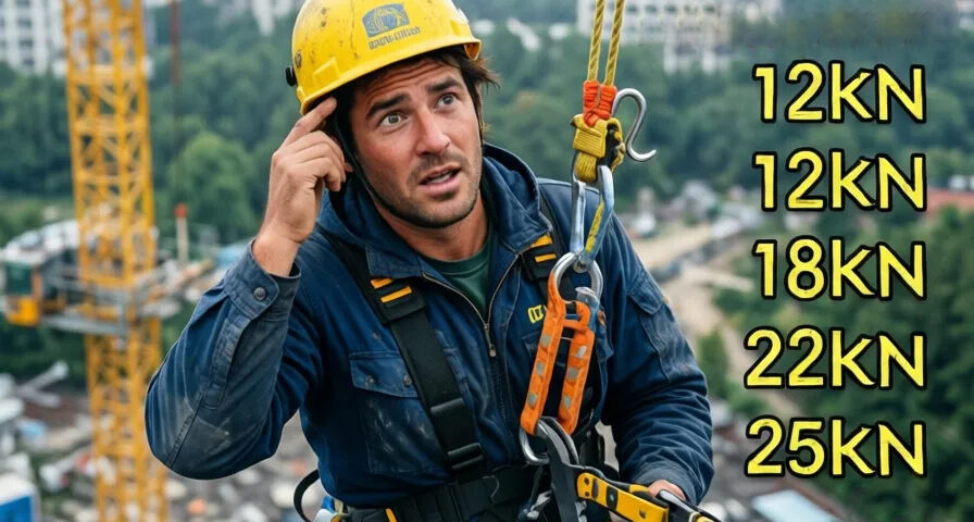
What Loads Does EN 795 Require of a Work-at-Height Anchor — and Why?
Where the numbers come from: the physics of a fall, the static test loads by anchor type, the safety factors, the catenary forces in a lifeline — and real lab results for two EN 795-rated ADIT products, the AAC anchor and the BTeye2 eye bolt.
In short
EN 795 is the core European standard for fall-protection anchor points. To understand the required loads you have to separate the forces acting during a fall from the safety factors the standard imposes. The chain runs: a fall generates a force limited to ~6 kN on the body; the standard doubles that to a 12 kN static test load for fixed anchors; lifelines (Type C) add catenary forces that can reach 20–40 kN at the end anchors. The article closes with real SATRA and destructive test results for the ADIT AAC and BTeye2.
1. The physical basis: Maximum Arrest Force (MAF)
The primary load is not the worker’s static weight — it is the kinetic energy generated in a free fall.
- Force limiting: most fall-arrest systems (energy absorbers) are designed to limit the force on the worker’s body to at most 6 kN (about 600 kg).
- Where the number comes from: physiological research found this to be the maximum force the human body can absorb in a harness without serious injury.
2. Static load requirements by anchor type
The standard divides anchor points into five types (A, B, C, D, E). For each, a static test load is set that the anchor must withstand without breaking.
- Fixed anchors (Type A, C, D): must withstand a static load of 12 kN.
- Temporary/portable anchors (Type B): 12 kN if made of metal, and 18 kN if made of textile materials (because of their sensitivity to wear).
- Dead-weight / friction anchors (Type E): must withstand a 12 kN test load, but their principal test is dynamic (arresting a dropped mass).
3. Safety factors
Why is the requirement 12 kN if the energy absorber limits the force to 6 kN? The standard applies a safety factor of 2 (double safety):
- 6 kN — the force expected in a fall.
- × 2 — a safety factor to ensure the structure and anchor hold even in extreme conditions, material fatigue or imperfect installation.
4. Dynamic loads in lifelines (Type C)
In flexible lifelines (steel cable) the load calculation is more complex because of the catenary effect:
- When a worker falls at the middle of a tensioned cable, the force transferred to the end points (the anchors) is significantly greater than the arrest force itself.
- The angle formed in the cable during the fall acts as a “force multiplier”.
- As a result, at lifeline end anchors the loads can easily reach 20–40 kN, depending on the line length and the number of simultaneous users. The line installer must provide an engineering plan detailing the exact end-point loads.
Practical application: lifeline loads with the ADIT BTeye2
Beyond the general requirements of the standard, the manufacturer’s official installation instructions carry decisive weight in fixing the load that actually applies. The ADIT BTeye2 instructions contain several critical points that bear directly on the loads the bolt can transfer in a lifeline (Type C):
- Permitted number of users: installed as a single anchor point (one anchor per person) the bolt is approved for one worker only; used as a lifeline end anchor (two anchors + cable) the manufacturer permits up to 3 people at once on the same line — which explains part of the wide spread in loads noted above.
- Dedicated lifeline embedment: a lifeline needs a minimum embedment of 120 mm in sound concrete, versus a minimum of just 8 cm as a single-person anchor point. The bolt’s pull-out capacity varies with embedment (roughly 11–14 cm for a lifeline) and the quality of the concrete.
- Two installation methods, and their effect on load direction: the manufacturer defines two approved methods — (1) two anchors working in shear, set at close to the optimal angle towards the floor edge; (2) two anchors working in tension, set perpendicular. The choice sets the direction of the force the anchor must carry.
- Limiting the direction of the force — critical for catenary loads: the manufacturer stresses that shear forces may be applied only in the plane of the bolt. In a shear-method lifeline installation the anchor must therefore be set perpendicular, with the eye of the bolt kept as close to the substrate as possible — otherwise the accumulated catenary load acts in a direction the bolt was not designed for, which can significantly reduce its effective capacity.
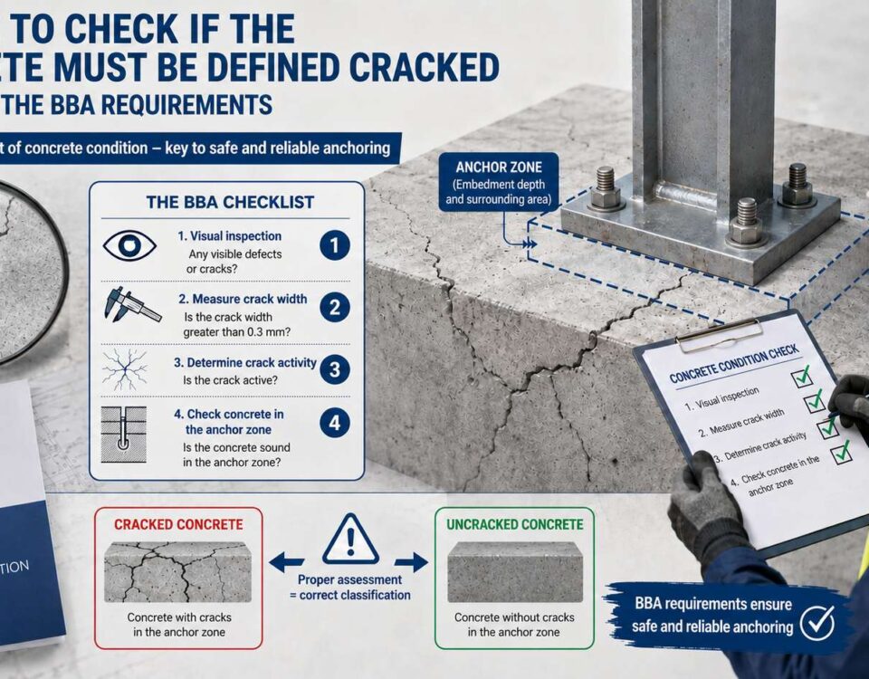
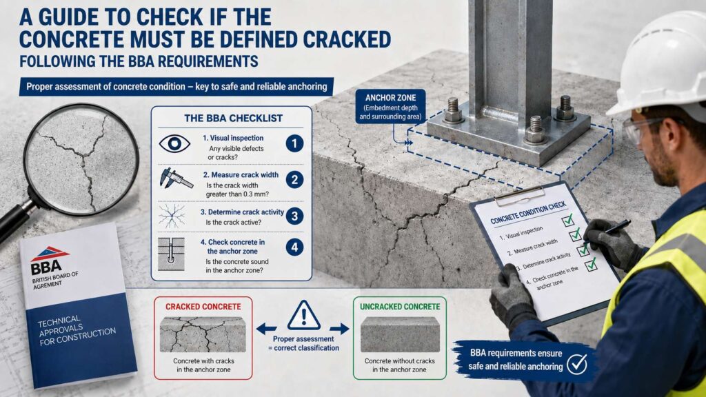
- Concrete quality limit: the bolt must not be installed in unsound concrete, or in concrete weaker than B20, without consulting the company engineer. Wherever there is any doubt about the quality of the concrete, carry out an actual pull-out test — like the Isotope tests set out below.
- Service-life limit: the bolt must not be used more than 5 times for work at height. Visible damage, a reduction in thread thickness or difficulty in threading calls for immediate replacement — the safe working load (SWL) assumes a sound bolt, not one carrying accumulated wear.
- Periodic inspection on permanent installations: the coating supplied with the bolt is only a 5–8 micron cold galvanising, so a permanent or long-term installation calls for close monitoring of corrosion spread at least once a year — in line with the annual periodic inspection required under EN 365.
Important: do not confuse a single anchor point with a lifeline anchor
The Fall Protection Equipment product tag attached to the BTeye2 as a single anchor point states explicitly “Number of users allowed: 1”. That limit changes only when the bolt is built into a designed lifeline system with two anchors and a cable, where it rises to a maximum of 3 users. Never assume a user limit without checking how the anchor was actually installed.
5. Design loads versus test loads
Two concepts must be kept apart:
- Proof / test load: the load the anchor must withstand in a pull-out test. Note that the anchor is usually tested under static loads, which can differ from its capacity under dynamic loads.
- Safe working load (SWL): the load allowed on the anchor including the appropriate safety factor, used mainly by a structural engineer to design the anchorage (for example for lifelines).
- Substrate requirement: the structure the anchor connects to (concrete, steel) must itself be able to carry the standard’s test loads with a further safety factor per the building codes.
Lab-proven capacities: the ADIT AAC and BTeye2 (both EN 795)
Both products were tested at the recognised British laboratory SATRA as Type A anchors to EN 795:2012, and underwent further destructive pull-out tests at the Isotope laboratory in Israel.
| Product | Test type | Direction | Result |
|---|---|---|---|
| ADIT AAC | Dynamic (SATRA, EN 795:2012) | Shear | Arrested a 150 kg mass, peak force 11.28 kN; 300 kg residual load held for 3 min |
| ADIT AAC | Dynamic (SATRA) | Tension | Arrested a 150 kg mass, peak force 10.26 kN; 300 kg residual load held 3 min |
| ADIT AAC | Static (SATRA) | Shear | Held 15 kN fully for 3 min; failed only at 26.58 kN — in the connecting bolt, not the anchor |
| ADIT AAC | Static (SATRA) | Tension | Held 15 kN fully for 3 min; failed only at 18.59 kN — in the connecting bolt, not the anchor |
| ADIT BTeye2 12×100 | Dynamic (SATRA, EN 795:2012) | Free fall | Arrested a 100 kg mass from a 4 m free fall (9 kN); 300 kg residual load held 3 min |
| ADIT BTeye2 12×100 | Static (SATRA) | — | Held 12 kN fully for 3 min with no failure |
| ADIT BTeye2 12×100 | Destructive pull-out (Isotope, concrete wall) | Tension | Failed in the concrete around the bolt (cracked concrete) at ~5.4–6.3 t (~53–62 kN); the bolt itself did not fail |
| ADIT BTeye2 12×140 | Destructive pull-out (Isotope, concrete wall) | Tension | Failed at the loop weld at ~9.7–10.5 t (~95–103 kN) |
What the results tell us
Both products clear the EN 795 requirements with a wide margin. In the AAC static tests the anchor itself never failed — the failure occurred in the connecting bolt, at 26.58 kN (shear) and 18.59 kN (tension), well above the 15 kN test level. The BTeye2’s destructive pull-out was limited by the surrounding concrete (53–62 kN in the 12×100) rather than the bolt, confirming that on sound concrete the anchor is far stronger than the standard demands.
- Both products were tested and passed every dynamic and static requirement of EN 795:2012 as Type A anchors, at the accredited SATRA laboratory in the UK.
- In the destructive pull-out tests we ran with the Isotope laboratory on the BTeye2, loads of several tonnes were needed to cause failure — roughly 5 to 10.5 t depending on the model — far above the standard’s minimum requirement of 12 kN (about 1.2 t).
- One clarification matters: destructive pull-out results also depend on the type and thickness of the wall being tested, and they are not a substitute for the safe working load (SWL) you actually design to. For that, work with a structural engineer and the manufacturer’s data.
Both products — the AAC tab anchor and the BTeye2 eye bolt — come with a complete standards file and independent laboratory testing, and are intended for use as a compliant anchor point under EN 795, together with the signage required by EN 365 that we cover in other articles on this site.
Common questions
What does a “Type A” anchor mean under EN 795?
A single fixed anchor point fastened directly to a load-bearing substrate such as concrete or steel, which has to pass the specific static and dynamic tests set out in the standard — exactly the tests the ADIT AAC and ADIT BTeye2 went through.
Is the pull-out load from a destructive test the load you can design to?
No. A destructive/failure load is not the design load. The safe working load (SWL) is much lower, because it includes the required safety factor. The destructive pull-out load — the tonnes recorded in the Isotope test — is a failure load under specific laboratory conditions. For real design work, use the loads set by the standard (for example 12 kN for the static test) with the appropriate safety factor, and with the approval of a structural engineer.
Why did the AAC static test fail in the connecting bolt and not the anchor?
Because the anchor itself is stronger than the connecting bolt. The failure at 26.58 kN (shear) / 18.59 kN (tension) was in the bolt — proof that the anchor’s own capacity exceeds the standard’s requirement. This is in fact a positive result: the capacity of the system is set by the weakest link in the chain, so the anchoring and connecting bolts should themselves be selected to match the design loads the project requires.
Sources
- EN 795:2012 — Personal fall-protection equipment: anchor devices.
- SATRA test reports (Type A, dynamic and static) for ADIT AAC and BTeye2.
- Isotope laboratory destructive pull-out reports (BTeye2 12×100 and 12×140).