

DIN 7504 – the standard for self-drilling (cladding) screws
12 בJuly 2026
How to identify your wall and choose the right plug
12 בJuly 2026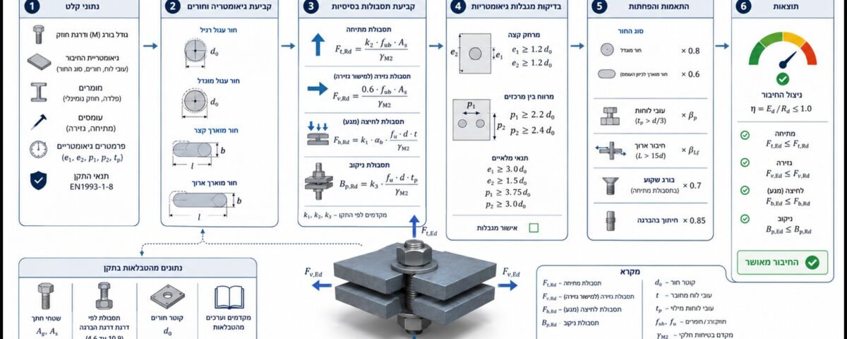
How to Calculate the Load Capacity of a Bolt and Nut — Full Design Guide to EN 1993-1-8:2005 (Section 3.8)
Eurocode 3’s core standard for steel-structure connections defines the strict engineering requirements for bolt-and-nut connections. Below is a comprehensive collection of the geometric dimensions, minimum distances, strength properties, and calculation formulas for shear, tension and bearing capacity.
In short
A bolt connection’s capacity is governed by four checks: bearing on the connected steel (depends on the plate steel grade and thickness), shear through the bolt (depends on the bolt grade and cross-section), tension in the bolt, and the combined shear-plus-tension interaction. All values below use the partial safety factor gamma-M2 of 1.25. Minimum edge and spacing distances must be kept to avoid tearing the plate, and special hole types (oversized, slotted) and connection cases (long joints, packing plates, countersunk bolts) carry defined reduction factors.
1. Dimensions, hole types and cross-section areas
| Bolt size | Nut width s (mm) | Diameter d (mm) | Normal hole d-o (mm) | Oversize d-o (mm) | Short slotted | Long slotted | Gross A-g (mm2) | Stress A-s (mm2) |
|---|---|---|---|---|---|---|---|---|
| M5 | 8 | 5 | 5.5 | – | – | – | 19.6 | 14.2 |
| M6 | 10 | 6 | 6.6 | – | – | – | 28.3 | 20.1 |
| M7 | 11 | 7 | 7.6 | – | – | – | 38.5 | 28.9 |
| M8 | 13 | 8 | 9.0 | 10.0 | 10 by 9 | 20 by 9 | 50.3 | 36.6 |
| M10 | 16 | 10 | 11.0 | 12.0 | 12 by 11 | 25 by 11 | 78.5 | 58.0 |
| M12 | 18 | 12 | 13.0 | 15.0 | 16 by 13 | 30 by 13 | 113.0 | 84.3 |
| M14 | 21 | 14 | 15.0 | 17.0 | 18 by 15 | 35 by 15 | 154.0 | 115.0 |
| M16 | 24 | 16 | 18.0 | 20.0 | 22 by 18 | 40 by 18 | 201.0 | 157.0 |
| M18 | 27 | 18 | 20.0 | 22.0 | 24 by 20 | 45 by 20 | 254.0 | 192.0 |
| M20 | 30 | 20 | 22.0 | 24.0 | 26 by 22 | 50 by 22 | 314.0 | 245.0 |
| M22 | 32 | 22 | 24.0 | 26.0 | 28 by 24 | 55 by 24 | 380.0 | 303.0 |
| M24 | 36 | 24 | 26.0 | 28.0 | 32 by 26 | 60 by 26 | 452.0 | 353.0 |
| M27 | 41 | 27 | 30.0 | 33.0 | 37 by 30 | 68 by 30 | 573.0 | 459.0 |
| M30 | 46 | 30 | 33.0 | 36.0 | 41 by 33 | 75 by 33 | 707.0 | 561.0 |
| M36 | 55 | 36 | 39.0 | 42.0 | 48 by 39 | 90 by 39 | 1018.0 | 817.0 |
2. Minimum distances from the edge and between bolts (EN 1993-1-8 Table 3.3)
The connection’s capacity depends on keeping minimum geometric distances to prevent tearing the plate. The distances are measured from the centre of the hole:
- e1 (edge distance in the load direction): minimum 1.2 times d-o.
- e2 (edge distance perpendicular to the load): minimum 1.2 times d-o.
- p1 (spacing between bolts in the load direction): minimum 2.2 times d-o.
- p2 (spacing between bolts perpendicular to the load): minimum 2.4 times d-o.
Adjustment for oversize and slotted holes: for these hole types, the minimum distances are not measured only from the hole centre; you must add to the rule above the difference between the enlarged radius and the normal hole radius, to ensure the amount of steel around the hole stays the same as for a normal hole.
3. Bearing resistance for the steel profile (F-b,Rd) by thickness
The bearing capacity depends on the strength of the connected steel (not the bolt strength), the bolt diameter (d), and the plate thickness (t). The capacity formula is:
The table below gives the maximum bearing capacity per 1 mm of plate thickness (in kN per mm). To get the total capacity, multiply the table value by the effective connected plate thickness (t). The calculation assumes correct edge distances allowing alpha-b of 1.0 and k1 of 2.5.
| Bolt size | S235 (f-u 360 MPa) kN per mm | S275 (f-u 430 MPa) kN per mm | S355 (f-u 490 MPa) kN per mm |
|---|---|---|---|
| M5 | 3.60 | 4.30 | 4.90 |
| M6 | 4.32 | 5.16 | 5.88 |
| M8 | 5.76 | 6.88 | 7.84 |
| M10 | 7.20 | 8.60 | 9.80 |
| M12 | 8.64 | 10.32 | 11.76 |
| M14 | 10.08 | 12.04 | 13.72 |
| M16 | 11.52 | 13.76 | 15.68 |
| M18 | 12.96 | 15.48 | 17.64 |
| M20 | 14.40 | 17.20 | 19.60 |
| M22 | 15.84 | 18.92 | 21.56 |
| M24 | 17.28 | 20.64 | 23.52 |
| M27 | 19.44 | 23.22 | 26.46 |
| M30 | 21.60 | 25.80 | 29.40 |
| M36 | 25.92 | 30.96 | 35.28 |
Bearing-capacity reductions for non-normal hole types
Per EN 1993-1-8 Section 3.8 (Table 3.4), the following reductions apply to the bearing values for special holes:
- For oversized holes: multiply the bearing capacity by a factor of 0.8.
- For slotted holes (when the long axis is perpendicular to the load direction): multiply the capacity by a factor of 0.6.
4. Single-plane shear design resistance (F-v,Rd, in kN)
The values are calculated with gamma-M2 of 1.25, assuming the shear plane passes through the threaded area.
| Bolt size | Grade 4.6 | Grade 4.8 | Grade 5.6 | Grade 5.8 | Grade 6.8 | Grade 8.8 | Grade 10.9 |
|---|---|---|---|---|---|---|---|
| M8 | 7.03 | 5.86 | 8.78 | 7.32 | 8.78 | 14.05 | 14.64 |
| M10 | 11.14 | 9.28 | 13.92 | 11.60 | 13.92 | 22.27 | 23.20 |
| M12 | 16.19 | 13.49 | 20.23 | 16.86 | 20.23 | 32.37 | 33.72 |
| M16 | 30.14 | 25.12 | 37.68 | 31.40 | 37.68 | 60.29 | 62.80 |
| M20 | 47.04 | 39.20 | 58.80 | 49.00 | 58.80 | 94.08 | 98.00 |
| M24 | 67.78 | 56.48 | 84.72 | 70.60 | 84.72 | 135.55 | 141.20 |
| M30 | 107.71 | 89.76 | 134.64 | 112.20 | 134.64 | 215.42 | 224.40 |
5. Tension design resistance (F-t,Rd, in kN)
| Bolt size | Grade 4.6 | Grade 4.8 | Grade 5.6 | Grade 5.8 | Grade 6.8 | Grade 8.8 | Grade 10.9 |
|---|---|---|---|---|---|---|---|
| M8 | 10.54 | 10.54 | 13.18 | 13.18 | 15.81 | 21.08 | 26.35 |
| M10 | 16.70 | 16.70 | 20.88 | 20.88 | 25.06 | 33.41 | 41.76 |
| M12 | 24.28 | 24.28 | 30.35 | 30.35 | 36.42 | 48.56 | 60.70 |
| M16 | 45.22 | 45.22 | 56.52 | 56.52 | 67.82 | 90.43 | 113.04 |
| M20 | 70.56 | 70.56 | 88.20 | 88.20 | 105.84 | 141.12 | 176.40 |
| M24 | 101.66 | 101.66 | 127.08 | 127.08 | 152.50 | 203.33 | 254.16 |
| M30 | 161.57 | 161.57 | 201.96 | 201.96 | 242.35 | 323.14 | 403.92 |
6. Combined load: shear-and-tension interaction
Per the standard, when a connection must carry tension and shear simultaneously, it must satisfy the following condition, using the design applied loads over the design resistances:
7. Full design rules and reduction factors (EN 1993-1-8 Section 3.8)
Per the technical specification and the manufacturer’s documents, apply the following notes and factors in geometric edge cases:
- Safety factor: the partial safety factor for bolt resistance at the ultimate limit state (ULS) is set at gamma-M2 of 1.25.
- Shear plane in the plain shank: if the shear plane passes through the unthreaded part, the effective area is A-g (gross area).
- Shear resistance factors: as detailed in the formulas, for bolt grades 4.6, 5.6 and 8.8 the shear factor alpha-v is 0.6. For the other grades (4.8, 5.8, 6.8, 10.9) the factor is 0.5.
- Tension: the tension capacity uses the threaded area A-s and a factor k2 that defaults to 0.9.
- Punching shear: the B-p,Rd capacity against the bolt head punching through the plate must be verified.
- Effect of packing plates: when the bolts pass through packing plates with a total thickness (t-p) greater than one-third of the bolt diameter (one-third of d), the design shear capacity F-v,Rd must be multiplied by the reduction factor beta-p (per Equation 3.3 in EN 1993-1-8).
- Long joints: for long joints, where the distance between the outermost bolt centres in the load-transfer direction exceeds 15 times the bolt diameter (15d), the shear capacity F-v,Rd of all bolts in the connection must be reduced by the factor beta-Lf (per Equation 3.5 in the standard).
- Hole reductions (Table 3.4): the bearing capacity F-b,Rd gets a factor of 0.8 in oversized holes, and 0.6 in slotted holes when the long axis is perpendicular to the load.
- Countersunk bolts: the tension capacity F-t,Rd is calculated using a factor k2 of 0.63 instead of 0.9, so in practice the calculated capacity drops to about 0.7 of the original. In addition, for the bearing capacity F-b,Rd, the plate thickness (t) is taken as the original plate thickness minus half the depth of the countersunk head.
- Cut threads: for bolts whose thread is made by cutting or machining (rather than rolling), if the thread does not meet the strict requirements of the relevant standard, special examinations and capacity verification are needed to prevent fatigue failures and stress concentration.
Sources
- EN 1993-1-8:2005 — Eurocode 3: Design of steel structures — Part 1-8: Design of joints (Section 3.8; Tables 3.3 and 3.4).
- ADIT bolt-and-nut technical catalogue (dimensions, cross-section areas, grade properties).