

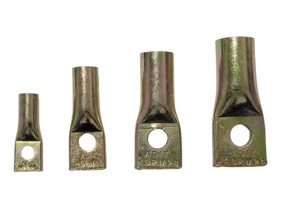
ADIT HSR Cast-in Concrete Insert
Internal threaded insert cast into concrete and connected to a bent rebar — for anchoring, lifting and connecting elements to cast concrete, in four sizes M12–M24 with factory pull-out test results.
Technical specification
| Property | ADIT HSR — cast-in concrete insert |
|---|---|
| Product type | Cast-in concrete insert (embedded before the pour) |
| Material | Cold Formed Carbon Steel |
| Coating | Zinc (Zn) 5–8 micron |
| Sizes | M12 / M16 / M20 / M24 |
| Internal thread | Metric standard (Rd) |
| Rebar connection | Required — bent rebar through transverse hole at the insert base |
| Installation stage | Before the pour (no drilling after curing) |
| Testing | Factory pull-out test — report 243105 (8 tests to failure, all 4 sizes) |
Downloads
ADIT HSR cast-in concrete insert — threaded insert for rebar connection
Every precast concrete element, every lifting point and every industrialised connection to cast concrete starts at a single anchoring point: the cast-in concrete insert. The ADIT HSR insert by Adit Ltd. is a threaded insert embedded in the concrete before the pour and connected to a bent rebar, so it “locks” itself inside the concrete mass and carries the tension and shear loads required in construction, industrial and infrastructure applications.
The HSR concrete insert is made of Cold Formed Carbon Steel and comes with a 5–8 micron zinc coating that gives it suitable durability for field conditions. The insert body contains a standard internal thread (M12 / M16 / M20 / M24) that lets you connect a bolt, lifting eye, tension rod, railing bracket or any other threaded element – after the concrete has cured, without drilling or installing a chemical anchor at a later stage.
Important to know: ADIT HSR is a rebar-dependent insert – the tension loads and the combined load in the technical table are conditional on a proper connection to a bent rebar of the diameter and length matching the insert size. An insert installed without a rebar, or with a rebar of a non-matching diameter, will not reach the loads shown in the specification.
What is a concrete insert and how does it work
A concrete insert is a metal component embedded within the concrete during the pouring stage (rather than screwed into cured concrete like a chemical anchor or a wedge anchor). The ADIT HSR insert has two complementary “anchorages”: the external shape of the insert body (cone/steps) that creates a mechanical lock within the concrete mass, and a transverse hole at the base of the insert through which a bent rebar is threaded – acting as an additional anchor and significantly increasing the total tension load.
After the concrete has cured, the installer reaches the top of the insert – which has a metric-standard internal thread (Rd) – and screws in the required element: a lifting eye bolt, a threaded rod for a railing connection, a bolt for an equipment bracket, and more. Because the thread already exists inside the concrete, there is no need for additional drilling, epoxy or a chemical anchor on site.
Single-anchor load table for ADIT HSR (conditional on rebar connection)
The following table, taken from Adit’s official technical data, shows the tension loads (Nu/Nrd/Nrec) and the combined load at 45° (Yu/YRd/Yrec) for each of the four insert sizes. All values are expressed in kN and include three levels: ultimate failure load (test result to failure), design load (after safety factors, for use in engineering calculations) and recommended / service load (recommended for routine field use).
| Insert size | Nu ultimate tension (kN) | Yu combined 45° ultimate (kN) | Nrd tension design load (kN) | YRd combined 45° design load (kN) | Nrec recommended tension (kN) | Yrec combined 45° service (kN) |
|---|---|---|---|---|---|---|
| M12 | 38.4 | 33.0 | 16.1 | 15.4 | 11.5 | 11.0 |
| M16 | 60.0 | 51.0 | 28.0 | 23.8 | 20.0 | 17.0 |
| M20 | 75.1 | 62.1 | 40.6 | 33.6 | 29.0 | 24.0 |
| M24 | 97.1 | 74.7 | 54.6 | 42.0 | 39.0 | 30.0 |
Please note: all values in the table are conditional on a proper rebar connection of the diameter and length matching the insert size (see the “General data” table below). The data refers to a single anchor; for multiple anchoring, keep the minimum distances from the concrete edge (cmin) and between anchors (smin), as detailed in the following table.
General data and dimensions – ADIT HSR insert
The following table brings together all the installation dimensions required for each insert size: insert body length, internal and external thread diameters, thread length, the diameter of the hole for inserting the rebar, the required rebar diameter, the required rebar length (before and after bending) and the recommended minimum distances.
| Parameter | M12 | M16 | M20 | M24 |
|---|---|---|---|---|
| Bolt / insert length H (mm) | 60 | 77 | 92 | 100 |
| Internal thread diameter Rd (mm) | 12 | 16 | 20 | 24 |
| External diameter D (mm) | 15 | 21 | 27 | 31 |
| Thread length E (mm) | 22 | 27 | 35 | 43 |
| Rebar insertion hole diameter F (mm) | 10 | 13 | 16 | 18 |
| Required rebar diameter dB (mm) | 8 | 10 | 12 | 14 |
| Rebar length per side LB (mm) | 240 | 330 | 440 | 480 |
| Rebar length before bending (mm) | 490 | 670 | 890 | 970 |
| Minimum rebar loop opening after bending dBr (mm) | 24 | 40 | 48 | 56 |
| Recommended minimum distance from concrete edge cmin (mm) | 40 | 45 | 50 | 65 |
| Recommended minimum distance between anchors smin (mm) | 60 | 75 | 90 | 100 |
| Part no. | 12060HSR | 16080HSR | 20090HSR | 24100HSR |
Bending the rebar is not optional. The rebar is supplied/prepared straight (for example 490 mm for M12) and is then bent into an arc/loop shape at a minimum opening diameter (dBr) as detailed in the table. The bend is what creates the locking effect within the concrete mass and allows the insert to reach the tension loads specified.
Pull-out test results – ADIT HSR insert (factory report 243105)
To verify the insert’s performance under controlled production conditions, Adit carried out a factory pull-out test (Factory Certification Pull-out Test, report no. 243105, dated 08-01-2024, tested by Eng. W. Huang). The test included 8 pull-out tests to failure across all four insert sizes: M12×60, M16×80, M20×90 and M24×100. The failure results (Breaking Load) were measured and presented in the following table.
| Insert size | Breaking Load in test (kN) |
|---|---|
| M12×60 | 46.0 |
| M16×80 | 66.5 |
| M20×90 | 90.2 |
| M24×100 | 106.8 |
Interpreting the results: the failure loads measured in the factory test (46.0–106.8 kN) are higher than the ultimate tension failure load (Nu) listed in the official load table (38.4–97.1 kN), because the factory test is carried out under controlled laboratory conditions. For actual engineering design, however, you should rely on the design load (Nrd/YRd) and recommended load (Nrec/Yrec) data in the main table, which match field conditions and the required safety factors.
Common applications for the ADIT HSR concrete insert
Thanks to the dual connection – a standard internal thread on one side and rebar anchorage on the other – the HSR insert suits a wide range of applications in construction, industry and infrastructure where a reliable connection point to concrete is needed, pre-embedded during the pouring stage:
- Precast concrete: embedding in precast concrete elements – beams, columns, walls and industrial structures – to create a future connection point for bolts.
- Lifting and hanging points: connecting lifting eyes or lifting brackets to the concrete element for moving, assembly and installation on site.
- Railings and scaffolding: an anchoring point for installing railing brackets, scaffolding and temporary or permanent protective frames on concrete surfaces.
- Equipment and system brackets: connecting brackets for HVAC systems, piping, rails and industrial equipment mounted on concrete surfaces.
- Wall cladding and panels: anchoring panels, stone/metal cladding and secondary structural elements to cast concrete walls.
- Formwork and dowel assemblies: use as a fixing point in formwork systems and industrial dowel assemblies that require a strong, repeatable threaded connection to concrete.
Correct installation of the ADIT HSR concrete insert – step by step
Unlike a chemical anchor or a wedge anchor, the HSR insert is installed before the pour and not afterwards. Incorrect installation – an improper rebar connection, wrong positioning within the formwork, or failure to keep minimum distances – will impair the loads the insert can actually carry. Follow these steps:
- Choosing the right rebar – choose a rebar of diameter dB matching the insert size (for example 8 mm for M12, 14 mm for M24) and cut it to the correct length before bending, as detailed in the general data table.
- Bending the rebar – bend the rebar into a loop/arc shape at an opening diameter no smaller than the required minimum (dBr) for the relevant insert size.
- Threading the rebar into the insert – thread the bent rebar through the transverse hole (F) at the base of the insert, so that both ends come out at an equal length LB on each side.
- Positioning in the formwork and fixing – fix the insert in the formwork at the correct direction and depth, and tie the rebar to the existing reinforcement in the formwork so it does not move during the pour. Keep the minimum distances from the concrete edge (cmin) and between adjacent anchors (smin).
- Pouring the concrete – pour the concrete so that it fully envelops the insert body and the bent rebar, with no voids or air pockets around them.
- Connecting the bolt after curing – after the concrete has cured to the required strength, screw the required element (eye bolt, threaded rod or bracket) into the internal thread (Rd), according to the working load required for the project.
What is allowed and recommended
- Use a rebar of the diameter and length exactly matching the insert size.
- Bend the rebar to an opening diameter (dBr) no smaller than the required minimum.
- Tie the rebar to the existing reinforcement to prevent movement during the pour.
- Keep the minimum distance from the concrete edge (cmin) for every anchor.
- Keep the minimum distance between adjacent anchors (smin).
- Check the internal thread for dust/concrete before connecting the bolt.
- Work to the design/recommended load (Nrd/Nrec) in engineering calculations.
What must not be done
- Install an insert without a rebar and rely on the table loads.
- Use a rebar of a diameter smaller than required for the insert size.
- Bend the rebar to an opening diameter smaller than the defined minimum (dBr).
- Position the insert closer than the minimum distance to the concrete edge.
- Leave air voids around the insert during the pour.
- Load the bolt beyond the design/recommended load without an engineer’s check.
- Install in concrete of unknown strength without checking engineering suitability.
Warning: all loads in the design table are conditional on a full, proper installation, including a connection to a suitable rebar. In any doubt regarding the insert size, the required rebar diameter or the concrete strength in the project – contact an Adit Ltd. engineer: +972-54-7976110.
Frequently asked questions about concrete inserts
What is a concrete insert and what is it used for?
What is the difference between a concrete insert and a wedge anchor or a chemical anchor?
How is the HSR insert installed – before or after the pour?
Which rebar diameter is required for each HSR insert size?
What is the recommended working load for each HSR insert size?
Why does the rebar need to be bent, and why can’t it be used straight?
What is the difference between tension load (Nu/Nrd) and combined 45° load (Yu/YRd)?
What is the minimum distance required from the concrete edge and between adjacent anchors?
Which tests have ADIT HSR inserts passed?
Which applications suit the HSR concrete insert?
Can bolts be connected and disconnected from the HSR insert in the future?
What is the coating of the HSR insert and why is it important?
Planning a project with cast-in inserts? Tell us the insert size, rebar diameter and load – our engineers will run the calculation and send you the HSR technical data.